The worldwide supply of multilayer ceramic capacitors (MLCCs) is not keeping up with demand. This is due in no small part to increased electronic complexity of cell phones, increased sales of electric cars, and a worldwide expansion of electronic content across industries. Some smartphones have doubled MLCC usage over a few years; an electric vehicle can quadruple usage over a typical modern internal combustion engine (Figure 1). The supply shortage of MLCCs, appearing near the end of 2016, has made it especially difficult to obtain large-capacity products (several tens of µF or more) necessary for the operation of prolific power supplies used in the latest electronics. Manufacturers looking to reduce their MLCC requirements inevitably look to the capacitor requirements of power supplies—in particular, switching regulators. This places power supply designers on the front lines of mitigating the cap shortage.
在全球范围内,多层陶瓷电容(MLCC)供不应求。很大部分原因是因为手机的电子复杂性提高、电动汽车的销售量增加,以及全球各行各业电子内容的扩展。相比几年前,一些智能手机的MLCC用量翻了一番;相比使用典型的现代内燃机的汽车,电动汽车的MLCC用量增加至少4倍(图1)。MLCC从2016年底开始缺货,这使得生产大电容值产品(几十µF或更高)变得尤其困难,而最新电子器件采用的高能电源需要这种电容才能运行。制造工厂想要降低MLCC要求不可避免地想要从电源的电容要求着手,尤其是开关稳压器的电容。因此,电源设计人员成为解决电容短缺问题的关键。

图1.全球范围内电动汽车(a)和手机(b)对MLCC的用量增加,但生产量没有相应增加,导致MLCC缺货。1
Power Circuits Use Capacitors, A Lot of Capacitors
电源电路使用电容——大量电容
A typical dc-to-dc buck converter uses the following capacitors (see Figure 2):
典型的直流-直流降压变换器使用下列电容(参见图2):
- Output capacitor: Smooths out both output voltage ripple and supply load current during load transients. Generally, a large capacitor measuring several tens of μF to 100 μF is used.
- 输出电容:在负载瞬态响应期间,平缓输出电压波纹和电源负载电流。一般使用几十μF到100 μF的大电容。
- Input capacitor: In addition to stabilizing the input voltage, it plays the role of instantaneously supplying the input current. In general, several μF to several tens of μF are used.
- 输入电容:除了稳定输入电压之外,它还被用于输入电流的即时供应。一般在几μF到几十μF之间。
-Bypass capacitor: Absorbs noise generated by switching operation and noise from other circuits. 0.01 μF to 0.1 μF are generally used.
- 旁路电容:吸收开关操作产生的噪声和来自其他电路的噪声。一般在0.01 μF到0.1 μF之间。
- Compensation capacitor: It secures the phase margin in the feedback loop and prevents oscillation. Several hundreds of pF or several tens of nF are often used. Some switching regulator ICs incorporate the compensation capacitor.
u 补偿电容:保证反馈回路中的相位裕量并防止振荡。通常为几百pF或几十nF。有些开关稳压器IC中采用了补偿电容。
The best way to reduce capacitance is to focus on minimizing the output capacitors. A strategy for reducing output capacitance is explored next, followed by solutions to reducing bypass capacitor requirements and, to some extent, input capacitors.
降低电容的最好方法是想办法最小化输出电容的数量。本文接下来将介绍减少输入电容的策略方法,然后介绍降低旁路电容要求,以及,在一定程度上,减少输入电容的解决方案。
Figure 2. Capacitors used in a typical buck regulator.
图2.典型降压稳压器使用的电容。
Increase Switching Frequency to Reduce Output Capacitance
增加开关频率,以降低输出电容
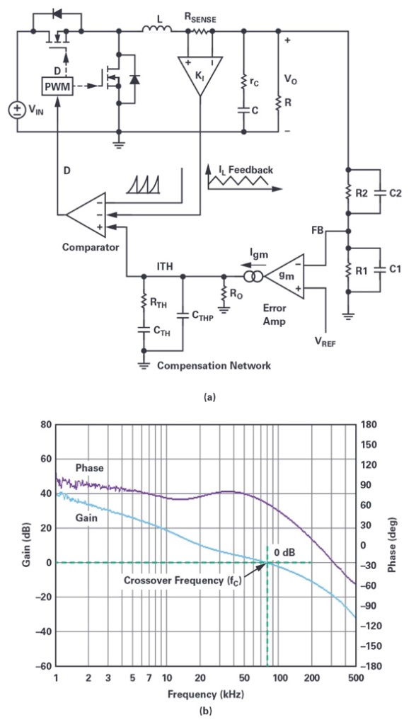
Figure 3a shows a typical current-mode buck converter block diagram, with the shaded area denoting the feedback loop and the compensation circuit.
图3a显示的是典型的电流模式降压变换器的框图,下部电路区域表示反馈回路和补偿电路。
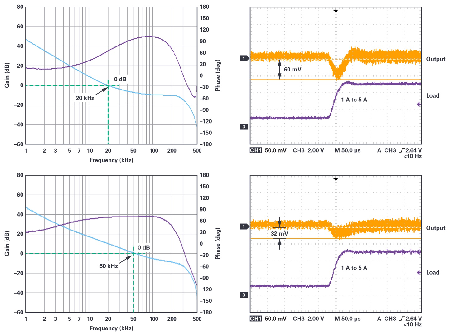
The characteristic of the feedback loop is shown in Figure 3b. The frequency at which the loop gain is 0 dB (gain = 1) is called the crossover frequency (fC). The higher the crossover frequency, the better the load step response of the regulator. For example, Figure 4 shows the load step response for a regulator supporting a rapid load current increase from 1 A to 5 A. The results are shown for crossover frequencies of 20 kHz and 50 kHz, resulting in 60 mV and 32 mV dropouts, respectively.
反馈回路的特性如图3b所示。回路增益为0 dB(增益=1)时的频率被称为交越频率(fC)。交越频率越高,稳压器的负载阶跃响应性能越出色。例如,图4显示的是支持负载电流从1A快速增加到5A的稳压器的负载阶跃响应。所示结果对应的交越频率为20 kHz和50 kHz,分别导致60 mV和32 mV压降。
Figure 3. Block diagram of a typical buck regulator (a) and typical feedback characteristic (b).
图3.典型降压稳压器(a)的框图和典型的反馈特性(b)。
Figure 4. Comparing the load step responses of a buck regulator at two crossover frequencies.
图4.比较采用两种交越频率时,降压稳压器的负载阶跃响应。
On the surface, increasing the crossover frequency looks like an easy choice: load step response is improved by minimizing the output voltage drop, so the output capacitor can be reduced. Raising the crossover frequency, though, brings up two issues. First, it is necessary to secure a sufficient phase margin of the feedback loop to prevent oscillation. Generally, a phase margin of 45° or more (preferably 60° or more) is required at the crossover frequency.
从表面上看,提高交越频率似乎是个简单方法:可以通过最小化输出压降来改善负载阶跃响应,从而减少输出电容数量。但是,提高交越频率会导致两个问题。第一,需要保证反馈回路具备足够的相位裕量,以防止振荡。一般来说,采用该交越频率时,需要45°或更高(最好是60°或以上)的相位裕量。
The other issue is the relationship between switching frequency (fSW) and fc. If they are similar in magnitude, negative feedback can respond to the output voltage ripple, threatening stable operation. As a guideline, set the crossover frequency to one-fifth (or less) of the switching frequency, as shown in Figure 5.
第二,需要注意开关频率(fSW)和fc之间的关系。如果它们的幅度相当,负反馈会响应输出电压波纹,从而影响到稳定运行。作为一项指导,可以将交越频率设置为开关频率的1/5(或更低),如图5所示。
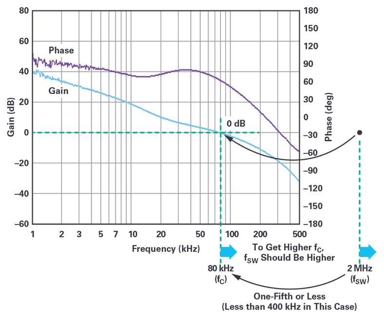
Figure 5. If the switching frequency and control loop crossover frequency are too close, the negative feedback may respond to output voltage ripple. It is best to keep the crossover frequency below one-fifth of the switching frequency.
图5.如果开关频率和控制回路交越频率太过接近,负反馈可能响应输出电压波纹。最好是让交越频率低于开关频率1/5。
To increase the crossover frequency, you must also raise the switching frequency, which in turn results in higher switching losses via the top and bottom FETs, reducing conversion efficiency and generating additional heat. Any savings in capacitance is offset by the complexity of additional heat mitigation components: fins, fans, or additional board space.
要增加交越频率,需要同时增加开关频率,但是,这会导致顶部和底部FET的开关损耗增加,会降低转换效率和产生更多热量。在电容上实现的节省会因为增加散热元件带来的复杂性抵消:比如鳍状散热器、风扇或额外的板空间。
Is it possible to maintain high efficiency at high frequency operation? The answer is yes. A number of Power by Linear™ regulator ICs from Analog Devices do just that by incorporating a unique FET control that keeps efficiency high even at higher switching frequencies (Figure 6).
是否能够在高频率下保持高效率?答案是肯定的。使用ADI公司提供的Power by Linear™稳压器IC就可以达到这种效果,这些稳压器IC采用独特的FET控制功能,在更高开关频率下也能保持高效率(图6)。
For example, the LT8640S 6 A output buck regulator maintains greater than 90% efficiency over its full load range (0.5 A to 6 A) while operating at a frequency of 2 MHz (12 V input and 5 V output).
例如,LT8640S 6 A输出降压稳压器在操作频率为2 MHz时(12V输入和5V输出),在整个负载范围内(0.5 A至6 A)能保持高于90%的效率。
This regulator also lowers the capacitance requirements by reducing inductor current ripple (ΔIL), which in turn reduces the output ripple voltage (ΔVOUT) as shown in Figure 7. Likewise, a much smaller inductor can be used.
这个稳压器也可以通过减少电流波纹(ΔIL)来降低电容要求,从而降低输出波纹电压(ΔVOUT),如图7所示。或者,使用更小的电感。
With a higher switching frequency, the crossover frequency can be increased, improving load step response and load regulation, as shown in Figure 8.
开关频率更高时,可以增加交越频率,以改善负载阶跃响应和负载调整,如图8所示。
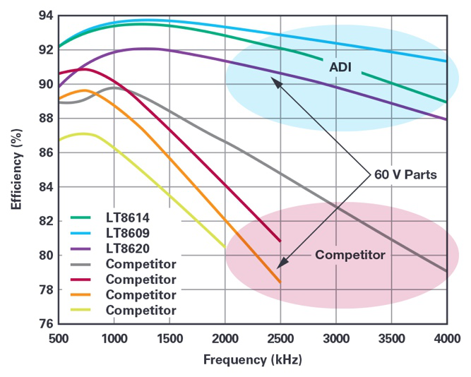
Figure 6. Power by Linear regulators vs. competition. In a typical regulator, when the switching frequency goes up, efficiency goes down. ADI Power by Linear regulators can maintain high efficiency at very high operating frequencies, enabling the use of smaller value output capacitors.
图6.Power by Linear稳压器与竞争产品。对于典型的稳压器,开关频率增高时,效率会下降。ADI的Power by Linear稳压器可以在非常高的操作频率下保持高效率,因而支持使用值更小的输出电容。
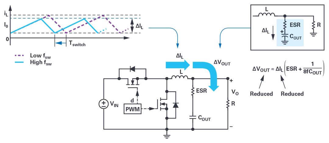
Figure 7. Increase switching frequencies to reduce capacitor and inductor size.
图7.通过增加开关频率来减小电容和电感的尺寸。

Figure 8. Increased switching frequency results in improved load step response.
图8.增加开关频率可以改善负载阶跃响应。
Silent Switcher Regulators Significantly Reduce Bypass Capacitance
Silent Switcher稳压器可以大幅降低旁路电容
How about reducing bypass capacitance? The main role of the bypass capacitor is to absorb the noise generated by switching operation itself. If switching noise is reduced in other ways, the number of bypass capacitors can be reduced. A particularly easy way to achieve this is through the use of a Silent Switcher® regulator.
如果减少旁路电容的数量,会如何?旁路电容主要被用于吸收开关操作产生的噪声。如果能从其他方面降低开关噪声,就可以减少旁路电容的数量。有一个特别简单的方法可以实现这种效果,即使用Silent Switcher®稳压器。
How does a Silent Switcher regulator reduce switching noise? A switching regulator has two current loops: when the top FET is on and the bottom FET is off (red loop) and when the top FET is off and the bottom FET is on (blue loop) as shown in Figure 9. The hot loop carries a fully switched ac current—that is, switched from zero to IPEAK and back to zero. It has the highest ac and EMI energy, as it produces the strongest changing magnetic field.
Silent Switcher稳压器如何降低开关噪声?开关稳压器具有两个电流回路:顶部FET开启,底部FET关闭(红色回路);顶部FET关闭,底部FET开启(蓝色回路),如图9所示。热回路传输完全开关的交流电流,也就是说,从0切换到IPEAK,然后回到0。它具备最高的交流和EMI能源,会产生最强变化的磁场。

Figure 9. The hot loop in a switching regulator produces the bulk of the radiated noise because of the alternating magnetic field it generates.
图9.开关稳压器中的热回路会因为本身产生的交变磁场而导致大量辐射噪声。
Slew-rate control can be used to suppress switching noise by slowing the rate of change of the gate signals (lowering di/dt). While effective in suppressing the noise, this increases switching losses, producing additional heat, especially at high switching frequencies as previously described. Slew-rate control is effective under certain conditions and Analog Devices also offers solutions with this feature.
可以使用压摆率控制来降低栅级信号变化的频率(降低di/dt),以便抑制开关噪声。这种方法虽然能够抑制噪声,但会增加开关损耗,导致产生更多热量,在之前所述的高开关频率下尤其如此。压摆率控制在某些条件下是有效的,ADI公司也提供包含这种控制的解决方案。
Silent Switcher regulators suppress electromagnetic noise generated from the hot loop without slew-rate control. Rather it splits the VIN pin in two, allowing the hot loop to be split into two symmetrical hot loops. The resulting magnetic field is confined to the area near the IC, and significantly reduced elsewhere, thus minimizing radiated switching noise (Figure 10).
Silent Switcher稳压器可以抑制热回路中产生的电磁噪声,但不是使用压摆率控制。而是将VIN引脚一分为二,令热回路可以分成两个对称的热回路。产生的磁场被限制在靠近IC的区域,其他位置大幅降低,从而最大限度地降低辐射开关噪声(图10)。

Figure 10. Patented Silent Switcher technology.
图10.获得专利的Silent Switcher技术。
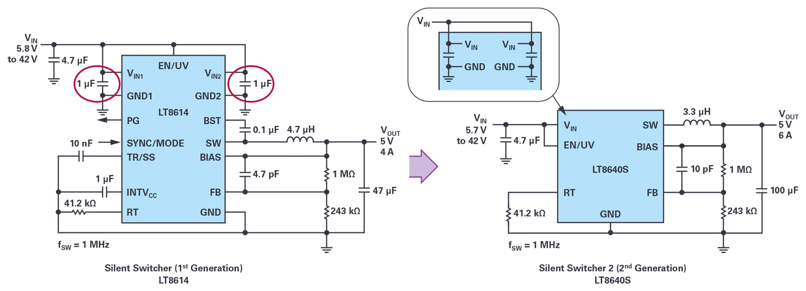
The LT8640S, the second generation of this technology—Silent Switcher 2 (Figure 11)—incorporates the input capacitors in the IC. This ensures maximum noise suppression, eliminating the need to carefully position the input caps in the layout. This feature, of course, also reduces the MLCC requirements. Another feature, spread spectrum frequency modulation, lowers noise peaks by dynamically changing the switching frequency. The combination of these features enables the LT8640S to clear CISPR 25 Class 5 EMC standards for automobiles with ease (Figure 12).
LT8640S是Silent Switcher技术的第二代,即Silent Switcher 2(图11),IC内部集成高频输入电容。这可以确保最大限度地抑制噪声,因此也无需如以前一样非常小心地在布局中确定输入电容的位置。毫无疑问,这也会降低对MLCC的要求。另一项功能——展频,会通过动态改变开关频率来降低噪声峰值。LT8640S兼具这些功能,因此能够轻松满足CISPR 25 5级EMC汽车标准(图12)。
Figure 11. Silent Switcher 2 technology from ADI brings the input caps within the IC, simplifying layout and improving noise suppression.
图11.ADI公司提供的Silent Switcher 2技术在IC中集成输入电容,由此简化布局和提升噪声抑制性能。
Figure 12. The combination of noise suppression features in a Silent Switcher 2 device, such as the LT8640S, enables easy clearance of CISPR 25 Class 5 peak limits even while reducing input and bypass capacitance.
图12.在Silent Switcher 2器件(例如LT8640S)中采用这些降噪功能使得产品能够轻松满足CISPR 25 5级峰值限值标准,甚至降低输入和旁路电容。
Conclusion
结论
Power by Linear devices from ADI can help reduce MLCC requirements, helping designers ride through the MLCC shortage. Output capacitance requirements are reduced by using high frequency operation while maintaining uncommonly high efficiency. Devices that feature Silent Switcher architecture significantly suppress EMI noise, reducing bypass capacitor requirements. Silent Switcher 2 devices further reduce MLCC needs.
ADI公司提供的Power by Linear器件有助于降低MLCC要求,从而帮助设计人员解决MLCC短缺问题。可以通过使用高频率操作来降低输出电容要求,同时保持出色的高效率。采用Silent Switcher架构的器件可以大幅抑制EMI噪声,从而降低旁路电容要求。Silent Switcher 2器件进一步降低了对MLCC的需求。
参考资料
1 Robin Blackwell. “Investor Presentation February 2018.” KEMET, February 2018.
1 Robin Blackwell。“投资演示,2018年2月。”KEMET,2018年2月。
LT8640S Data Sheet. Analog Devices, Inc., June 2017.
LT8640S数据手册。ADI公司,2017年6月。
Seago, John. “OPTI-LOOP Architecture Reduces Output Capacitance and Improves Transient Response.” Analog Devices, Inc., August 2007.
Seago, John。“OPTI-LOOP架构降低了输出电容,改善了瞬态响应。”ADI公司,2007年8月。
Zhang, Henry J. “Modeling and Loop Compensation Design of Switching Mode Power Supplies.” Analog Devices, Inc., February 2016.
Zhang, Henry J. “开关模式电源的模型和回路补偿设计。”ADI公司,2016年2月。
作者简介
Atsuhiko Furukawa于2006年加入凌力尔特(现在已成为ADI公司的一部分)。10多年以来,他一直为中小型客户提供多种应用技术支持。2017年,他被调到汽车部门,现在主要负责设计大型(几kW)和小型安全汽车应用。Atsuhiko是一名马拉松长跑健将,取得的最好成绩是3小时3分钟。


